


AS5311 Linear Encoder Boards
Low cost, high resolution linear encoder modules.
The ne plus ultra - and industry standard - of CNC motion-control systems is a closed-loop controller with linear encoders. Unfortunately, commercial linear encoders tend to be far too expensive for low-cost hobby CNC systems, as the cheapest setup (DRO scales, re-purposed as controller inputs) runs well over $500, comparable to the entire budget of some projects. Yet proper closed-loop control allows a machine designer to compensate for a number of otherwise-unavoidable sources of error prevalent in hobby-grade (ie. cheap) linear motion, such as thread lead error, thread drunkenness, step size non-linearity, skipped steps due to motor torque limits, etc
One possible solution to the high cost of commercial pre-packaged encoders is Austria Microsystem’s AS5311 magnetic linear encoder IC. For an affordable price ($9, quantity one), the AS5311 has some very nice specifications:
High resolution (488 nm) and decent accuracy (~5-10µm) - the accuracy is ultimately determined by the multipole magnetic tape.
A reasonable maximum travel speed (2.3 m/s), comparable to the upper limits of the fastest 3D printers and far exceeding that of DIY CNC mills.
Flexible controller interface, supporting
absolute
PWM and SPI and incremental quadrature outputs.
As the AS5311 seemed interesting enough to warrant further investigation, I sampled a few of them from AMS (along with magnetic tape) and built break-out boards. I haven’t gotten around to integrating them into a full control-system (although a friend’s masters thesis did!), but the breakout boards have proven to be quite useful. In particular, they’re very convenient for continuously measuring variations in 3D-printer filament diameter and any other application where a digital test indicator like a Mitutoyo 575 would be appropriate.
Revision One
Revision one of the board had a number of errors (thanks, hasty 2AM PCB layout), included two critical pins that weren’t corrected. However, a single flywire was sufficient to bring rev 1 into a usable state, and all of Ben’s thesis work proceeded using the initial set of three boards.
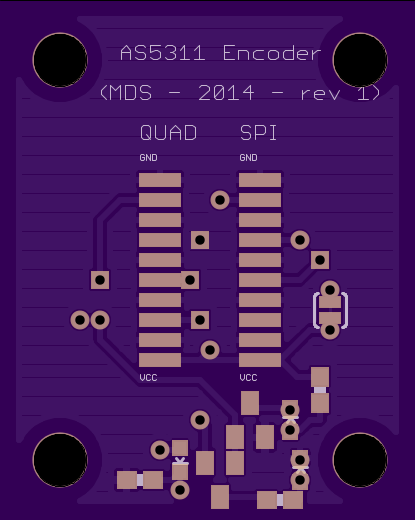
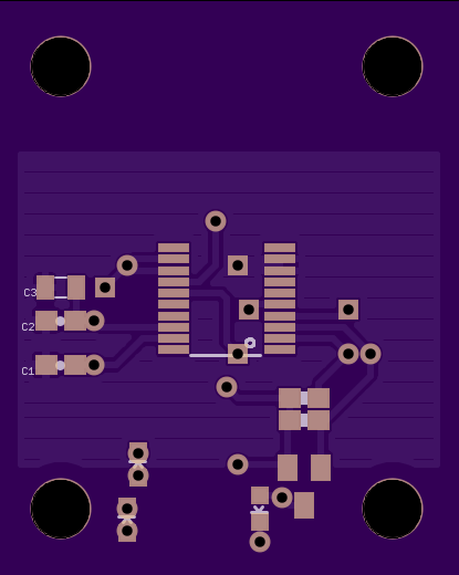
Fig 1: Revision 1, front and back
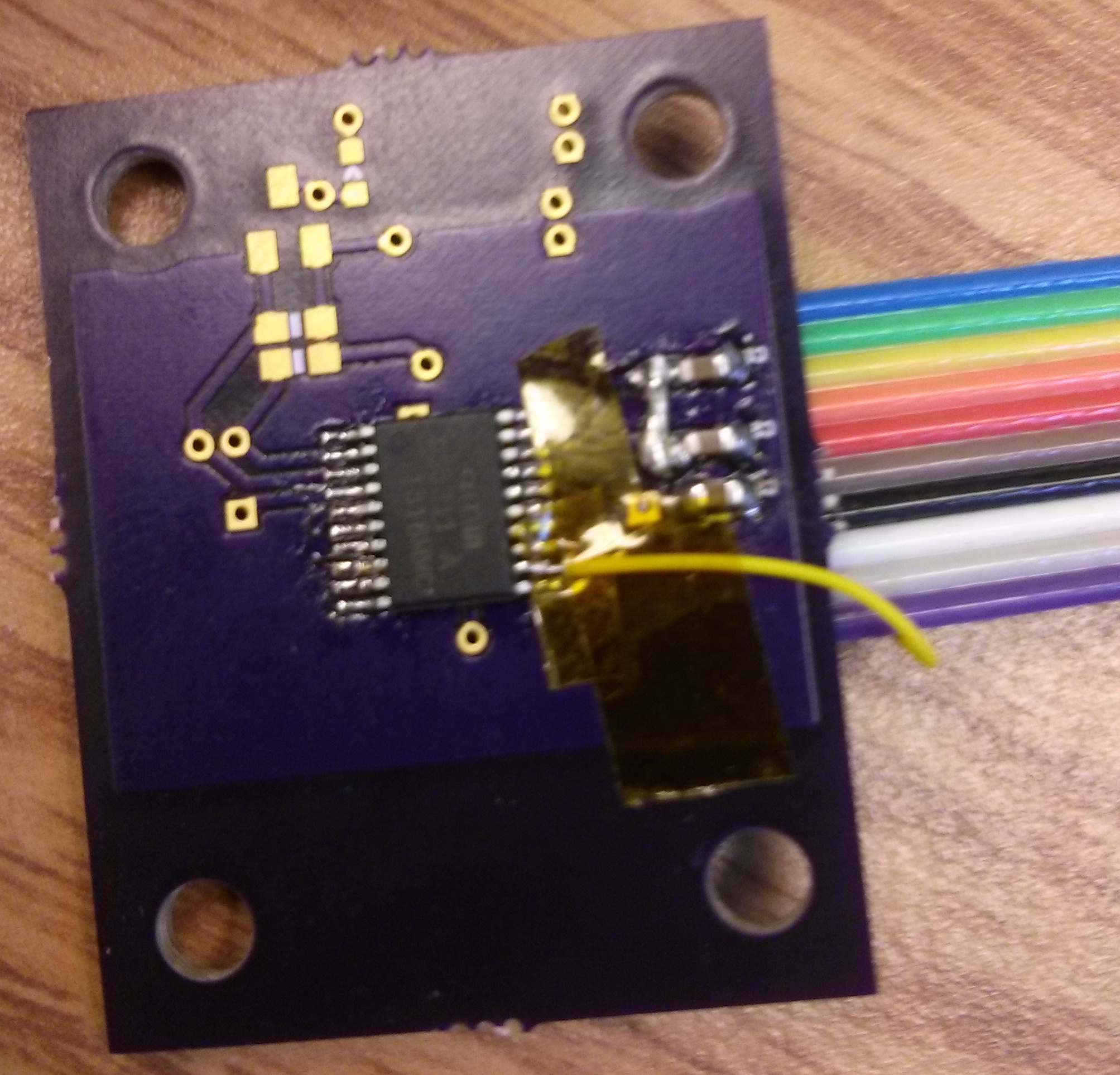
Fig 2: Ben’s flywire fix for the unconnected pin
Revision Two
Revision two of the encoder board has all of the issues with unconnected pins from revision one fixed, but is otherwise the exactly the same. All component population should be fairly straightforwards - consult the schematic for unlabeled components such as LEDs and FETs. For 3.3V operation, capacitor C3 is optional (although probably a good idea) and the jumper should be left as is. For 5V operation C3 is required and the jumper’s trace MUST be cut.
| AS5311 Breakout | Rev 1 | Part # | Quantity | Cost Per | |
|---|---|---|---|---|---|
| Board | NA | OSHPark | 1 | 2.25 | |
| AS5311-ATSU | U1 | Mouser | 985-AS5311-ATSU | 1 | 9.66 |
| 0.1μF 0603 | C1, C2 | Mouser | 2 | 0.01 | |
| 1μF 0805 | C3 | Mouser | 1 | 0.10 | |
| BSS84 p-chan FET | Q1, Q3 | Mouser | 512-BSS84 | 2 | 0.24 |
| BSS123 n-chan FET | Q2 | Mouser | 512-BSS123 | 1 | 0.24 |
| 0603 Red LED | D1 | Mouser | LS Q976-NR-1 | 1 | 0.10 |
| 0603 Green LED | D2 | Mouser | LG L29K-G2J1-24-Z | 1 | 0.22 |
| 0603 Yellow LED | D3 | Mouser | LY Q976-P1S2-36 | 1 | 0.10 |
| 0603 5K Ohm | R1, R2 | Mouser | 1 | 0.01 | |
| 0603 300 Ohm | R3, R4, R5 | Mouser | 1 | 0.01 |
All files and documentation pertaining to these encoder modules are relased under CC Attribution-ShareAlike 4.0 International.